Friday, December 20, 2013
Thursday, December 19, 2013
Spectroscopy,metals analysis
Spectrographic metals analysis is usually the 'heart' of most oil analysis programs. Using either a Rotrode Emission Spectrometer or an Inductively Coupled Plasma Spectrometer (ICP), 20 or more metals can be simultaneously determined. The metals analyzed for include wear, additive, and contaminant metals and are reported in parts per million (ppm).
Laboratories uses a Rotating Disk Emission Spectrometer. The instrument is quick and easy to operate and is accurate within acceptable limits.
The Rotrode Spectrometer has a particle size detection limitation of between 3µ and 10µ (depending on the particular metal in question and the amount of surface oxidation on the particle surface) compared to the .5µ - 2µ limitation of the ICP. Results of the Rotrode Spectrometer are accurate to about 1 or 2 ppm.
Results of the ICP are accurate to .1 ppm. The advantage of the Rotrode Spectrometer is that no dilution of the sample is required, while the advantage of the ICP is its accuracy. With proper sample preparation, an ICP can measure in the 10's of parts per billion (ppb).
Particle size limitations of an ICP are even more sever than a Rotrode Spectrometer because the sample and particles have to be nebulized. If measuring very low concentrations, the diluent (usually diesel fuel) has to be at least as clean.
Wednesday, December 18, 2013
Tuesday, December 17, 2013
Hot lay-up, Cold lay-up
Hot lay-up
Hot lay-up condition, the machinery is kept in operation for the sake of fast re-commissioning, but measures
may be taken to reduce various operational costs.
Cold lay-up
In cold lay-up condition the machinery is taken out of service and the vessel is kept “electrically dead” with the
exception of emergency power.
Single Phasing of a Motor?
Single Phasing of a Motor?
Single Phasing is where one of the 3-phase's supplying the Motor becomes disconnected. The Motor will continue to run if this happens and can result in Motor Burnout. The effect of Single Phasing is to increase the Current in the two remaining Lines and cause the Motor to become very noisy due to uneven Torque produced
How is 15ppm reached in an Oily Water Separator?
How is
15ppm reached in an Oily Water Separator?
15ppm is
achieved in an Oily Water Separator by normally passing through a Two Stage
Separator where in the first stage Oil/Water is passed into the coarse
separating compartment. Here some oil will rise to the top of the Compartment
due to its lower density, Heating Coils may aid this.
The remaining Oil/Water will flow down into
the Fine separating Compartment and moves slowly between Catch Plates. More Oil will separate out onto the underside
of these Plates and travel outwards until free to rise to the oil collecting
space.
The almost Oil Free Water
(usually being at 100ppm at this stage) will then pass to the second stage of
the separator, which is a Filter Unit comprising of two Filter Units.
The first Filter Stage removes Physical
Impurities present and promotes some Fine Separation.
The second Stage Filter uses Coalescer Inserts
to achieve the fina, Oil/Water Mixture leaving this Stage at less
than 15ppm.
Why is Simultaneous Injection of Fuel Oil and Starting Air into a Main Engine Cylinder Undesirable and How is it Prevented?
Why is
Simultaneous Injection of Fuel Oil and Starting Air into a Main Engine Cylinder
Undesirable and How is it Prevented?
Simultaneous
Injection of Fuel and Starting Air into a Cylinder is Undesirable as it could
lead to an Explosion in the Start Air System.
It is
prevented by means of Interlock, which prevents Fuel being Injected when the
Air Start Auto Valve is Open.
The
Interlock Operates a Stop Solenoid, which keeps the Fuel Rack at Zero Position.
What are the Safety Devices fitted to an Air Compressor?
What are
the Safety Devices fitted to an Air Compressor?
Low Lub
Oil Pressure Shut Down
High Air
Temperature Shut Down
1st Stage
Relief Valve
2nd Stage
Relief Valve
A Fusible
Plug is fitted after the 2nd Stage Cooler, Set at 120°C
If Water
Cooled, a Jacket Water Safety Valve is fitted.
What is the Primary Function of the Expansion Valve in a Refrigeration System?
What is
the Primary Function of the Expansion Valve in a Refrigeration System?
The
Primary Function of an Expansion Valve in a Refrigeration System is to regulate
the Flow of Refrigerant from the H P side to the L P side of the System.
The
pressure drop causes the Saturation Temperature to drop, enabling it to boil
off at the Low Temperature of the Evaporator.
Cloverleafing-
Cloverleafing-
When the cyl l.o. has inadequate acid neutralising properties for the fuel being burnt or if there is insufficient quantity of oil injected then cloveleafing can occur
This is basically regions of corrosive wear midway between the quills and upwards towards the top of the liner. These areas may be visible due to the corrosive effect and they are cloverleaf shaped.
Eventually the rings become unsupported in these areas, gas builds up on the front face and the ring is subject to collapse.


Improved High Lift safety valve material
Materials
for all parts must be non corrodible. Common materials are Bronze, Stainless
steel or Monel metal, depending on the conditions of service. The valve chest
is normally made of cast steel.
Boiler Burner Refractories
Refractories
A
material in solid form which is capable of maintaining its shape at high tempo
(furnace tempo as high as 1650oC) have been recorded.
Purpose
i. To
protect blr casing from overheating and distortion and the possible resulting
leakage of gasses into the machinery space.
ii. To reduce
heat loss and ensure acceptable cold faced temperature for operating personnel
iii. To
protect exposed parts of drum and headers which would otherwise become
overheated. Some tubes are similarly protected.
iv. Act as a
heat reservoir.
v. To be
used to form baffles for protective purposes or for directing gas flow.
Properties
i. Must have
good insulating properties.
ii. Must be
able to withstand high tempo's
iii. Must have
the mechanical strength to resist the forces set up by the adjacent refractory.
iv. Must be
able to withstand vibration.
v. Must be
able to withstand the cutting and abrasive action of the flame and dust
vi. Must be
able to expand and contract without cracking Note: no one refractory can be
used economically throughout the boiler
Types
i. Acid
materials- clay, silica, quartz , sandstone etc
ii. Neutral
materials-chromite, graphite, plumbago, alumina
iii. Alkaline
or base materials- lime, magnesia, zirconia
Forms
i. Firebricks-
these are made from natural clay containing alumina , silica and quartz. They
are shaped into bricks and fired in a kiln
ii. Monolithic
refractories- These are supplied in the unfired state, installed in the boiler
and fired in situ when the boiler is commissioned.
iii. Mouldable
refractory- This is used where direct exposure to radiant heat takes place. It
must be pounded into place during installation . It is made from natural clay
with added calcided fire clay which has been chrushed and graded.
iv. Plastic
chrome ore- This is bonded with clay and used for studded walls. It has little
strength and hence stud provides the support.
v. Castable
refractory-This is placed over water walls and other parts of the boiler were
it is protected from radiant heat . It is installed in a manner similar to
concreteing in building
vi. Insulating
materials- Blocks, bricks , sheets and powder are usually second line
refractories. I.E. Behind the furnace refractory which is exposed to the flame.
Material; asbestos millboard, magnesia , calcined magnesia block, diatomite
blocks, vermiculite etc. all having very low heat conductivity.
Purpose of fitting a Deaerator
Purpose of fitting a Deaerator
There are four main purposes;
·
To act as a storage tank so as to maintain a
level of water in the system
·
To keep a constant head on the feed system
and in particularly the Feed pumps.
·
Allow for mechanical deaeration of the water
·
Act as a contact feed heater.
Wednesday, December 11, 2013
Tuesday, December 10, 2013
Saturday, December 7, 2013
Pitchometer
Pitchometer
Top quality zinc-plated measuring device for exact determination of the diameter and pitch of marine
propellers

Top quality zinc-plated measuring device for exact determination of the diameter and pitch of marine
propellers

Thursday, December 5, 2013
Monday, December 2, 2013
lifting appliances
Why are lifting appliances ‘thoroughly examined’
A lifting appliance generally has no ‘redundancy’– so a single failure is enough to cause a major accident.
Various national regulatory schemes require that lifting appliances
should be thoroughly examined by a ‘competent person’ at least once every 12 months. Some legal frameworks may require more frequent examinations, depending on the national authority, the competent person, and whether the equipment is used for lifting personnel.
Lifting appliances are examined in accordance with
two main legal frameworks, depending on the type of equipment and its purpose.
•
Ships’ deck cranes, engine room cranes, and lifting equipment are examined in accordance with:
- the Merchant Shipping Regulations
- flag state requirements
- International Labour Organization (ILO) Convention 152, where it applies.
Ship-mounted life saving appliances are examined in accordance with:
- Safety Of Life At Sea (SOLAS) 1974
- International Maritime Organization (IMO) LSA Code
- the IMO Maritime Safety Committee (MSC) circulars
- individual flag state requirements.
Classification societies such as Lloyd’s Register offer two survey and examination services
for lifting appliances (excluding LSA davits):
• certification
• classification
Classification is used in two situations:
• Mandatory – where the lifting appliance is the essential feature of a classed
ship. This applies for example to a heavy lift crane on a heavy lift barge, or lifting
arrangements for diving operations on diving support ships.
• Optional – when the owner requests classification, even though the lifting appliance
may not be an essential feature of a classed ship.
Sunday, December 1, 2013
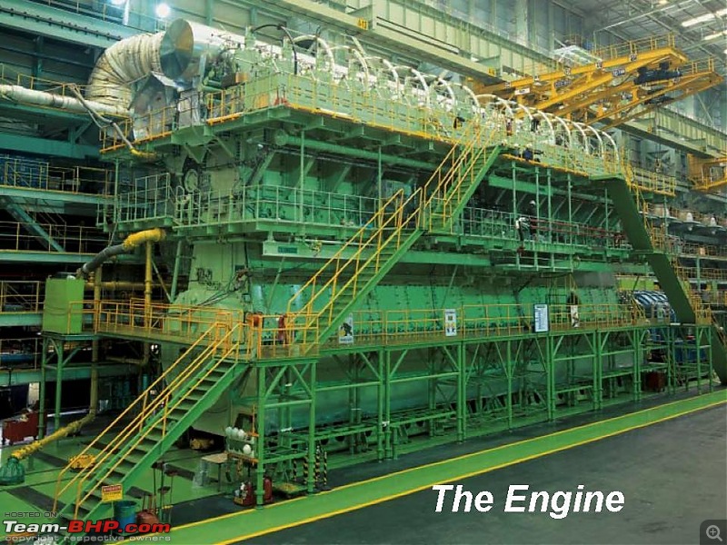
Engine Structure Rt flex 50
Engine Structure Rt flex 50
Wärtsilä RT-fl ex50 engines have a wellproven
type of structure, with a ‘gondola’-type
bedplate surmounted by very rigid, A-shaped
double-walled columns and cylinder block,
all secured by pre-tensioned vertical tie rods.
The whole structure is very sturdy with low
stresses and high stiffness. Both bedplate and
columns are welded fabrications which are
also designed for minimum machining.
A high structural rigidity is of major
importance for the today’s two-stroke engine’s
long stroke. Accordingly the design is based on
extensive stress and deformation calculations
carried out by using a full three-dimensional
fi nite-element computer model for different
column designs to verify the optimum frame
confi guration.
The double-walled column has thick guide
rails for greater rigidity under crosshead shoe
forces. The RT-fl ex supply unit is carried on
supports on one side of the column and the
scavenge air receiver on the other side of the
cylinder jacket. Access to the piston underside
is normally from the supply unit side, but
is also possible from the receiver side of the
engine, to allow for maintenance of the piston
rod gland and also for inspecting piston rings.
The cylinder jacket is a single-piece castiron
cylinder block with a high rigidity. The
cylinder liners are seated in the cylinder block,
and are sufficiently robust to carry the cylinder
covers without requiring a support ring. A light
sleeve is applied to upper part of each liner to
form a water jacket.
The tilting-pad thrust bearing is integrated
in the bedplate. Owing to the use of gear
wheels for the supply unit drive, the thrust
bearing can be very short and very stiff, and
can be carried in a closed, rigid housing.
precautions involved in running with Sulzer RT flex
1. What are the precautions involved in running with RT flex
Reliability and safety has the utmost priority
in the common rail RT-flex system.
v
The
duplicated high-pressure delivery pipes have stop cocks at both ends to isolate
any failed pipe. Each single pipe is adequate for the full delivery. All high
pressure pipes are double-walled for safety.
v
Every
injection nozzle is independently monitored and controlled by the WECS. In case
of difficulties, such as a broken high pressure line or a malfunctioning
injector, the affected injection valve can be cut out individually without
losing the entire cylinder.
v
If
the stroke measuring sensor fails, the WECS system switches the ICU to a pure
time control and triggers the signal based on the timing of the neighbouring
cylinders.
What is MSDS of fuel oil
Material Safety Data Sheet for Fuel oil
SECTION 1. PRODUCT AND COMPANY IDENTIFICATION
Product name : Fuel Oil
Synonyms : Bunkers, Black Fuel Oil, MFO, Industrial Fuel Oil, 6 Oil, Slurry Fuel Oil, RFO,
Refinery Fuel Oil, High Sulfur Fuel Oil, HSFO, IFO-30, IFO-180, IFO-380, IFO-
510, Bunker Fuel Oil, Marine Fuel Oil, Decant Oil, LSFO,
MSDS Number :
Product Use Description : Fuel,
Company :
SECTION 2. HAZARDS IDENTIFICATION
Emergency Overview
Regulatory status : This material is considered hazardous by the Occupational Safety and Health
Administration
Signal Word : WARNING
Hazard Summary
Potential Health Effects
EYE:
SKIN:
INGESTION:
INHALATION:
Chronic Exposure:
SECTION 3. COMPOSITION/INFORMATION ON INGREDIENTS
Clarified oils (petroleum),
catalytic cracked;
Heavy Fuel oil
Polycyclic aromatic compounds (PACs or PNAs)
Benzo[a]pyrene;
Benzo[def]chrysene
Hydrogen Sulfide
SulfuR
SECTION 4. FIRST AID MEASURES
Eye contact:
Skin contact
Inhalation
SECTION 5. FIRE-FIGHTING MEASURES
Form : Liquid
Flash point : 65.5°C (150°F) Minimum
Suitable extinguishing media : Carbon dioxide (CO2), Water spray
Special protective equipment :
for fire-fighters
Specific hazards during fire
fighting
SECTION 6. ACCIDENTAL RELEASE MEASURES
Personal precautions
Environmental precautions
Methods for cleaning up
SECTION 7. HANDLING AND STORAGE
SECTION 8. EXPOSURE CONTROLS / PERSONAL PROTECTION
SECTION 9. PHYSICAL AND CHEMICAL PROPERTIES
Colour : dark brown
Form : Liquid
SECTION 10. STABILITY AND REACTIVITY
SECTION 11. TOXICOLOGICAL INFORMATION
SECTION 12. ECOLOGICAL INFORMATION
SECTION 13. DISPOSAL CONSIDERATIONS
SECTION 14. TRANSPORT INFORMATION
What is the Rocking Test?
It is a test which is carried out to find, wear down of the
sleeve bearing of the deck crane on ships.
this measures the play (or relative movement) between the inner
and outer bearing race, to give an indication of the wear taking place.
(Wear down of the sleeve bearing can be found by analysing the grease sample.
The metal content of the sample may give indication of wear down.)
The Rocking Test need to be carried out according to manufacturer
recommendation
Measurements are typically taken in four positions on
the slew bearing, with the jib pointing:
• forward to the ship
• starboard
• aft
• port side.
Neither a load nor any cargo handling equipment should be attached to the hook.
It is important for the same positions to be marked as a datum reference..
Subscribe to:
Posts (Atom)