Friday, December 20, 2013
Thursday, December 19, 2013
Spectroscopy,metals analysis
Spectrographic metals analysis is usually the 'heart' of most oil analysis programs. Using either a Rotrode Emission Spectrometer or an Inductively Coupled Plasma Spectrometer (ICP), 20 or more metals can be simultaneously determined. The metals analyzed for include wear, additive, and contaminant metals and are reported in parts per million (ppm).
Laboratories uses a Rotating Disk Emission Spectrometer. The instrument is quick and easy to operate and is accurate within acceptable limits.
The Rotrode Spectrometer has a particle size detection limitation of between 3µ and 10µ (depending on the particular metal in question and the amount of surface oxidation on the particle surface) compared to the .5µ - 2µ limitation of the ICP. Results of the Rotrode Spectrometer are accurate to about 1 or 2 ppm.
Results of the ICP are accurate to .1 ppm. The advantage of the Rotrode Spectrometer is that no dilution of the sample is required, while the advantage of the ICP is its accuracy. With proper sample preparation, an ICP can measure in the 10's of parts per billion (ppb).
Particle size limitations of an ICP are even more sever than a Rotrode Spectrometer because the sample and particles have to be nebulized. If measuring very low concentrations, the diluent (usually diesel fuel) has to be at least as clean.
Wednesday, December 18, 2013
Tuesday, December 17, 2013
Hot lay-up, Cold lay-up
Hot lay-up
Hot lay-up condition, the machinery is kept in operation for the sake of fast re-commissioning, but measures
may be taken to reduce various operational costs.
Cold lay-up
In cold lay-up condition the machinery is taken out of service and the vessel is kept “electrically dead” with the
exception of emergency power.
Single Phasing of a Motor?
Single Phasing of a Motor?
Single Phasing is where one of the 3-phase's supplying the Motor becomes disconnected. The Motor will continue to run if this happens and can result in Motor Burnout. The effect of Single Phasing is to increase the Current in the two remaining Lines and cause the Motor to become very noisy due to uneven Torque produced
How is 15ppm reached in an Oily Water Separator?
How is
15ppm reached in an Oily Water Separator?
15ppm is
achieved in an Oily Water Separator by normally passing through a Two Stage
Separator where in the first stage Oil/Water is passed into the coarse
separating compartment. Here some oil will rise to the top of the Compartment
due to its lower density, Heating Coils may aid this.
The remaining Oil/Water will flow down into
the Fine separating Compartment and moves slowly between Catch Plates. More Oil will separate out onto the underside
of these Plates and travel outwards until free to rise to the oil collecting
space.
The almost Oil Free Water
(usually being at 100ppm at this stage) will then pass to the second stage of
the separator, which is a Filter Unit comprising of two Filter Units.
The first Filter Stage removes Physical
Impurities present and promotes some Fine Separation.
The second Stage Filter uses Coalescer Inserts
to achieve the fina, Oil/Water Mixture leaving this Stage at less
than 15ppm.
Why is Simultaneous Injection of Fuel Oil and Starting Air into a Main Engine Cylinder Undesirable and How is it Prevented?
Why is
Simultaneous Injection of Fuel Oil and Starting Air into a Main Engine Cylinder
Undesirable and How is it Prevented?
Simultaneous
Injection of Fuel and Starting Air into a Cylinder is Undesirable as it could
lead to an Explosion in the Start Air System.
It is
prevented by means of Interlock, which prevents Fuel being Injected when the
Air Start Auto Valve is Open.
The
Interlock Operates a Stop Solenoid, which keeps the Fuel Rack at Zero Position.
What are the Safety Devices fitted to an Air Compressor?
What are
the Safety Devices fitted to an Air Compressor?
Low Lub
Oil Pressure Shut Down
High Air
Temperature Shut Down
1st Stage
Relief Valve
2nd Stage
Relief Valve
A Fusible
Plug is fitted after the 2nd Stage Cooler, Set at 120°C
If Water
Cooled, a Jacket Water Safety Valve is fitted.
What is the Primary Function of the Expansion Valve in a Refrigeration System?
What is
the Primary Function of the Expansion Valve in a Refrigeration System?
The
Primary Function of an Expansion Valve in a Refrigeration System is to regulate
the Flow of Refrigerant from the H P side to the L P side of the System.
The
pressure drop causes the Saturation Temperature to drop, enabling it to boil
off at the Low Temperature of the Evaporator.
Cloverleafing-
Cloverleafing-
When the cyl l.o. has inadequate acid neutralising properties for the fuel being burnt or if there is insufficient quantity of oil injected then cloveleafing can occur
This is basically regions of corrosive wear midway between the quills and upwards towards the top of the liner. These areas may be visible due to the corrosive effect and they are cloverleaf shaped.
Eventually the rings become unsupported in these areas, gas builds up on the front face and the ring is subject to collapse.


Improved High Lift safety valve material
Materials
for all parts must be non corrodible. Common materials are Bronze, Stainless
steel or Monel metal, depending on the conditions of service. The valve chest
is normally made of cast steel.
Boiler Burner Refractories
Refractories
A
material in solid form which is capable of maintaining its shape at high tempo
(furnace tempo as high as 1650oC) have been recorded.
Purpose
i. To
protect blr casing from overheating and distortion and the possible resulting
leakage of gasses into the machinery space.
ii. To reduce
heat loss and ensure acceptable cold faced temperature for operating personnel
iii. To
protect exposed parts of drum and headers which would otherwise become
overheated. Some tubes are similarly protected.
iv. Act as a
heat reservoir.
v. To be
used to form baffles for protective purposes or for directing gas flow.
Properties
i. Must have
good insulating properties.
ii. Must be
able to withstand high tempo's
iii. Must have
the mechanical strength to resist the forces set up by the adjacent refractory.
iv. Must be
able to withstand vibration.
v. Must be
able to withstand the cutting and abrasive action of the flame and dust
vi. Must be
able to expand and contract without cracking Note: no one refractory can be
used economically throughout the boiler
Types
i. Acid
materials- clay, silica, quartz , sandstone etc
ii. Neutral
materials-chromite, graphite, plumbago, alumina
iii. Alkaline
or base materials- lime, magnesia, zirconia
Forms
i. Firebricks-
these are made from natural clay containing alumina , silica and quartz. They
are shaped into bricks and fired in a kiln
ii. Monolithic
refractories- These are supplied in the unfired state, installed in the boiler
and fired in situ when the boiler is commissioned.
iii. Mouldable
refractory- This is used where direct exposure to radiant heat takes place. It
must be pounded into place during installation . It is made from natural clay
with added calcided fire clay which has been chrushed and graded.
iv. Plastic
chrome ore- This is bonded with clay and used for studded walls. It has little
strength and hence stud provides the support.
v. Castable
refractory-This is placed over water walls and other parts of the boiler were
it is protected from radiant heat . It is installed in a manner similar to
concreteing in building
vi. Insulating
materials- Blocks, bricks , sheets and powder are usually second line
refractories. I.E. Behind the furnace refractory which is exposed to the flame.
Material; asbestos millboard, magnesia , calcined magnesia block, diatomite
blocks, vermiculite etc. all having very low heat conductivity.
Purpose of fitting a Deaerator
Purpose of fitting a Deaerator
There are four main purposes;
·
To act as a storage tank so as to maintain a
level of water in the system
·
To keep a constant head on the feed system
and in particularly the Feed pumps.
·
Allow for mechanical deaeration of the water
·
Act as a contact feed heater.
Wednesday, December 11, 2013
Tuesday, December 10, 2013
Saturday, December 7, 2013
Pitchometer
Pitchometer
Top quality zinc-plated measuring device for exact determination of the diameter and pitch of marine
propellers

Top quality zinc-plated measuring device for exact determination of the diameter and pitch of marine
propellers

Thursday, December 5, 2013
Monday, December 2, 2013
lifting appliances
Why are lifting appliances ‘thoroughly examined’
A lifting appliance generally has no ‘redundancy’– so a single failure is enough to cause a major accident.
Various national regulatory schemes require that lifting appliances
should be thoroughly examined by a ‘competent person’ at least once every 12 months. Some legal frameworks may require more frequent examinations, depending on the national authority, the competent person, and whether the equipment is used for lifting personnel.
Lifting appliances are examined in accordance with
two main legal frameworks, depending on the type of equipment and its purpose.
•
Ships’ deck cranes, engine room cranes, and lifting equipment are examined in accordance with:
- the Merchant Shipping Regulations
- flag state requirements
- International Labour Organization (ILO) Convention 152, where it applies.
Ship-mounted life saving appliances are examined in accordance with:
- Safety Of Life At Sea (SOLAS) 1974
- International Maritime Organization (IMO) LSA Code
- the IMO Maritime Safety Committee (MSC) circulars
- individual flag state requirements.
Classification societies such as Lloyd’s Register offer two survey and examination services
for lifting appliances (excluding LSA davits):
• certification
• classification
Classification is used in two situations:
• Mandatory – where the lifting appliance is the essential feature of a classed
ship. This applies for example to a heavy lift crane on a heavy lift barge, or lifting
arrangements for diving operations on diving support ships.
• Optional – when the owner requests classification, even though the lifting appliance
may not be an essential feature of a classed ship.
Sunday, December 1, 2013
Engine Structure Rt flex 50
Engine Structure Rt flex 50
Wärtsilä RT-fl ex50 engines have a wellproven
type of structure, with a ‘gondola’-type
bedplate surmounted by very rigid, A-shaped
double-walled columns and cylinder block,
all secured by pre-tensioned vertical tie rods.
The whole structure is very sturdy with low
stresses and high stiffness. Both bedplate and
columns are welded fabrications which are
also designed for minimum machining.
A high structural rigidity is of major
importance for the today’s two-stroke engine’s
long stroke. Accordingly the design is based on
extensive stress and deformation calculations
carried out by using a full three-dimensional
fi nite-element computer model for different
column designs to verify the optimum frame
confi guration.
The double-walled column has thick guide
rails for greater rigidity under crosshead shoe
forces. The RT-fl ex supply unit is carried on
supports on one side of the column and the
scavenge air receiver on the other side of the
cylinder jacket. Access to the piston underside
is normally from the supply unit side, but
is also possible from the receiver side of the
engine, to allow for maintenance of the piston
rod gland and also for inspecting piston rings.
The cylinder jacket is a single-piece castiron
cylinder block with a high rigidity. The
cylinder liners are seated in the cylinder block,
and are sufficiently robust to carry the cylinder
covers without requiring a support ring. A light
sleeve is applied to upper part of each liner to
form a water jacket.
The tilting-pad thrust bearing is integrated
in the bedplate. Owing to the use of gear
wheels for the supply unit drive, the thrust
bearing can be very short and very stiff, and
can be carried in a closed, rigid housing.
precautions involved in running with Sulzer RT flex
1. What are the precautions involved in running with RT flex
Reliability and safety has the utmost priority
in the common rail RT-flex system.
v
The
duplicated high-pressure delivery pipes have stop cocks at both ends to isolate
any failed pipe. Each single pipe is adequate for the full delivery. All high
pressure pipes are double-walled for safety.
v
Every
injection nozzle is independently monitored and controlled by the WECS. In case
of difficulties, such as a broken high pressure line or a malfunctioning
injector, the affected injection valve can be cut out individually without
losing the entire cylinder.
v
If
the stroke measuring sensor fails, the WECS system switches the ICU to a pure
time control and triggers the signal based on the timing of the neighbouring
cylinders.
What is MSDS of fuel oil
Material Safety Data Sheet for Fuel oil
SECTION 1. PRODUCT AND COMPANY IDENTIFICATION
Product name : Fuel Oil
Synonyms : Bunkers, Black Fuel Oil, MFO, Industrial Fuel Oil, 6 Oil, Slurry Fuel Oil, RFO,
Refinery Fuel Oil, High Sulfur Fuel Oil, HSFO, IFO-30, IFO-180, IFO-380, IFO-
510, Bunker Fuel Oil, Marine Fuel Oil, Decant Oil, LSFO,
MSDS Number :
Product Use Description : Fuel,
Company :
SECTION 2. HAZARDS IDENTIFICATION
Emergency Overview
Regulatory status : This material is considered hazardous by the Occupational Safety and Health
Administration
Signal Word : WARNING
Hazard Summary
Potential Health Effects
EYE:
SKIN:
INGESTION:
INHALATION:
Chronic Exposure:
SECTION 3. COMPOSITION/INFORMATION ON INGREDIENTS
Clarified oils (petroleum),
catalytic cracked;
Heavy Fuel oil
Polycyclic aromatic compounds (PACs or PNAs)
Benzo[a]pyrene;
Benzo[def]chrysene
Hydrogen Sulfide
SulfuR
SECTION 4. FIRST AID MEASURES
Eye contact:
Skin contact
Inhalation
SECTION 5. FIRE-FIGHTING MEASURES
Form : Liquid
Flash point : 65.5°C (150°F) Minimum
Suitable extinguishing media : Carbon dioxide (CO2), Water spray
Special protective equipment :
for fire-fighters
Specific hazards during fire
fighting
SECTION 6. ACCIDENTAL RELEASE MEASURES
Personal precautions
Environmental precautions
Methods for cleaning up
SECTION 7. HANDLING AND STORAGE
SECTION 8. EXPOSURE CONTROLS / PERSONAL PROTECTION
SECTION 9. PHYSICAL AND CHEMICAL PROPERTIES
Colour : dark brown
Form : Liquid
SECTION 10. STABILITY AND REACTIVITY
SECTION 11. TOXICOLOGICAL INFORMATION
SECTION 12. ECOLOGICAL INFORMATION
SECTION 13. DISPOSAL CONSIDERATIONS
SECTION 14. TRANSPORT INFORMATION
What is the Rocking Test?
It is a test which is carried out to find, wear down of the
sleeve bearing of the deck crane on ships.
this measures the play (or relative movement) between the inner
and outer bearing race, to give an indication of the wear taking place.
(Wear down of the sleeve bearing can be found by analysing the grease sample.
The metal content of the sample may give indication of wear down.)
The Rocking Test need to be carried out according to manufacturer
recommendation
Measurements are typically taken in four positions on
the slew bearing, with the jib pointing:
• forward to the ship
• starboard
• aft
• port side.
Neither a load nor any cargo handling equipment should be attached to the hook.
It is important for the same positions to be marked as a datum reference..
Saturday, November 30, 2013
What is the TMON?
TMON is the Tail shaft Monitering.
advantages as follows.
advantages as follows.
Purpose
To offer operators the opportunity to avoid withdrawing the tail shaft if indications show that the tail shaft and stern tube bearing and its systems are working satisfactorily.
Benefits
- Avoids time-consuming operations during dry docking
- Avoids the risk of damaging to the system during withdrawal
- Reduces costs
- Achieves an opportunity to monitor that the condition of the stern tube bearing and tail shaft are in good condition due to the system being followed up. When the system is properly implemented, the crew will be able to foresee possible damage and take preventive action
Features
This class notation is applicable to conventional propulsion systems. Tail shaft monitoring implies monitoring of the stern tube bearing, water content of the lub oil and litre lub oil refilled:
- The stern tube bearings are oil lubricated.
- A high-temperature alarm is fitted on the aft stern tube bearing.
- Where one interchangeable sensor is fitted, one spare sensor is to be stored on board.
- The setting of the stern tube high-temperature alarm should not exceed 65°C.
- The sealing rings in the stern tube sealing box must be replaceable without having to withdraw the shaft or remove the propeller.
- A system for measuring bearing wear must be fitted.
- Electrical grounding of the shafting is mandatory.
- The system must allow representative oil samples to be taken for an analysis of the oil quality under running conditions.
A written procedure for how to take oil samples is to be evaluated.
TMON gives the owner the opportunity to leave the tail shaft in position without pulling it out of the stern tube provided:
- The technical requirements are met.
- The TMON Record File is kept updated.
- Oil samples are regularly analysed and found to be satisfactory by a recognised laboratory.
- All stern tube bearing temperature values are within the manufacturer's recommended or limit values.
Reasons to fail the Tie Rods
1. Uneven and not properly tight the tie rods.
2. Material failure.
3. Scavange fires
4. Over tight of the tie rods
5. Secondary forces are not properly balanced
6. Fluctuation of thermal load and compression loads due
to bad weather or malfunction of fuel oil system.
2. Material failure.
3. Scavange fires
4. Over tight of the tie rods
5. Secondary forces are not properly balanced
6. Fluctuation of thermal load and compression loads due
to bad weather or malfunction of fuel oil system.
What are the purposes of Tie Rods
1. It holds cylinder block, A frame and bed plate together
2. Transfer the firing and compression pressures (tensile stresses) to the bed plate.
3.The tensile stresses which creating during compression and firing may cause fatigue failure
of engine component, which eliminate by the tie rods.
3. Because of it fitted close to crank shaft, prevent bending of transverse girders.
Monday, November 18, 2013
Sunday, November 17, 2013
T he Colombo Dockyard launched a 400 Passenger cum 250 Ton Cargo Vessel 'MV Corals'
Friday, November 15, 2013
T he Colombo Dockyard launched a 400 Passenger cum 250 Ton Cargo Vessel 'MV Corals'
T he Colombo Dockyard launched a 400 Passenger cum 250 Ton Cargo Vessel 'MV Corals' Thursday, built for the Union Territory of Lakshadweep Administration, Government of India. Shri J. Ashok Kumar Secretary PSA — UTLA took part in the launch. This is the first of two vessels being built.
The launching ceremony was attended to
by Shri P. Migdad, Director PSA-UTLA, Capt. Venunath PMS LDCL, Shri B.P.
Rai Vice President SB-SCI, Shri. B. Chakravarty General Manager
TS&SB-Sd, Ms. V. Lalitha Devi DM- Sd, Shri Manish Counselor -
Economic & Commercial of the Indian High Commission.
The vessel is designed by world renowned
ship design company, Global Maritime Brevik AS of Norway (formerly
known as GL Noble Denton/ Brevik Engineering) and the detailed design
engineering is performed by Neilsoft Ltd of India. This cooperation
enabled the convergence of specialists in their respective fields to
achieve the best design solutions and Colombo Dockyard performed the
arduous task of product realization.
The vessel is dually classed meeting
class rules of Lloyds Register of Shipping and Indian Register of
Shipping and statutory rules applicable for a vessel of this type.
The Passengers will have different
categories of accommodation. There will be 10 first class, 40 second
class and 350 normal class passenger transportation facilities. All
passenger compartments shall be fully air conditioned using an air
conditioning system consisting of central air handling unit and
refrigerating plant, designed on the basis of environment friendly
refrigerant chilled water system.
The Vessel is to be manned by a crew of
69 who will also be provided with comfortable and elegant living
quarters matching the world standards available on a vessel of this
class.
Saturday, November 16, 2013
Friday, November 15, 2013
Ship control system leading supliers
Lyngsø Marine are one of the worlds leading suppliers of advanced
marine automation equipment, marketed under the Stella® brand name.
Founded in the 1950s, Lyngsø have installed over 6,800 systems worldwide
and boast an impressive knowledge and expertise that is unrivalled in
their market sector.
Lyngsø have an impressive in-house R&D department dedicated to ensuring that their Stella systems incorporate state of the art technologies to remain at the head of their field. Their extensive product range includes Stella 2100 automation systems that cover alarm and control systems, and main engine control systems. Lyngsø automation systems cover many different applications from fully integrated ship control systems to small stand-alone alarm systems.
Lyngsø have an impressive in-house R&D department dedicated to ensuring that their Stella systems incorporate state of the art technologies to remain at the head of their field. Their extensive product range includes Stella 2100 automation systems that cover alarm and control systems, and main engine control systems. Lyngsø automation systems cover many different applications from fully integrated ship control systems to small stand-alone alarm systems.
Stella 2100 automation systems
Lyngsø's Stella automation systems are based upon modular units connected by a duplicated high-speed network which provides read out parameters and machinery control anywhere on a ship. Stella systems are flexible in their use and can be used with new installations and retrofits.Alarm and control systems for shipping applications
Lyngsø have developed a range of alarm and control systems that can meet almost all needs, these include:- UMS 2100 universal monitoring system: used for alarm monitoring of ship machinery and navigation instruments; UMS and Watch One notation is achieved through the use of intelligent alarm panels in the accommodation areas and on the bridge
- UCS 2100 universal monitoring and control system: combines alarm and control functions using distributed computers with several subsystems to meet the vessel requirements in a cost effective manner
- CMS 2100 reefer container monitoring system: monitoring and logging of reefer alarms and events is carried out through the electric power supply to the container onboard or ashore
- Naval platform control system: control and surveillance system for naval vessels enabling full control of the platform to be taken on the bridge or in the machinery control room through a fully duplicated set of operator stations with full colour graphic visual display units
Main engine control systems
- DMS 2100 diesel manoeuvring system: a complete bridge control system which supports two-stroke engines with fixed pitch propeller, including MAN B&W and Wärtsilä NSD; the system offers fully automatic remote control of the main engine from bridge and engine control room
- DPS 2100 diesel protection system: provides the stand-alone engine safety system for emergency shutdown or automatic power reduction to protect the propulsion system against damage
- EGS 2000 electronic governor system: for accurate control of the speed of large two-stroke diesel engines in a fuel efficient manner, even at low RPMs; provides automatic overspeed prevention in heavy seas through an automatic operating mode selection
- PCS 2100 propulsion control system: offers integrated machinery control and monitoring in a simple and easy-to-use fashion; the modular system is tailored to suit the vessel combinations of engines, propellers, clutches and control positions
Tuesday, November 12, 2013
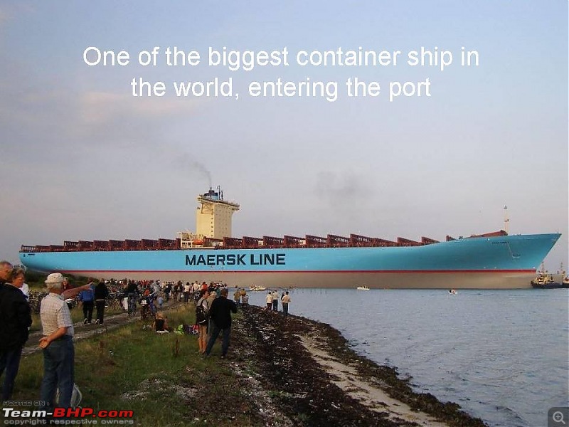
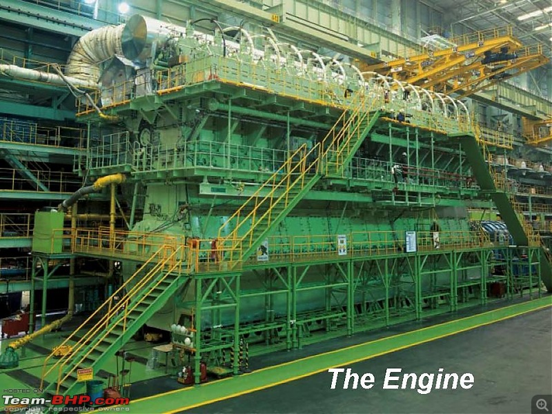
THE MOST POWERFUL ENGINE IN THE WORLD
THE MOST POWERFUL ENGINE IN THE WORLD: The Wartsila-Sulzer RTA96-C turbocharged two-stroke diesel engine
The Wartsila-Sulzer RTA96-C turbocharged two-stroke diesel engine is the most powerful and most efficient prime-mover in the world today. The Aioi Works of Japan’s Diesel United, Ltd built the first engines and is where some of these pictures were taken.
It is available in 6 through 14 cylinder versions, all are inline engines. These engines were designed primarily for very large container ships. Ship owners like a single engine/single propeller design and the new generation of larger container ships needed a bigger engine to propel them.
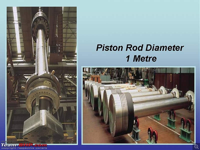
The cylinder bore is just under 38″ and the stroke is just over 98″. Each cylinder displaces 111,143 cubic inches (1820 liters) and produces 7780 horsepower. Total displacement comes out to 1,556,002 cubic inches (25,480 liters) for the fourteen cylinder version.
| Some facts on the 14 cylinder version: | ||
| Total engine weight: | 2300 tons (The crankshaft alone weighs 300 tons.) | |
| Length: | 89 feet | |
| Height: | 44 feet | |
| Maximum power: | 108,920 hp at 102 rpm | |
| Maximum torque: | 5,608,312 lb/ft at 102rpm | |
For comparison, most automotive and small aircraft engines have BSFC figures in the 0.40-0.60 lbs/hp/hr range and 25-30% thermal efficiency range.
Even at its most efficient power setting, the big 14 consumes 1,660 gallons of heavy fuel oil per hour.
Sunday, November 10, 2013
Ships Main Engine
Thrust Block
In a marine
engine the function of the thrust block, propeller shaft, and stern tube are
closely related, being responsible for the efficient transmission of the
engine’s power to the propeller and ensuring the control of torque and
propeller shaft alignment from the thrust block to the stern tube.
The "Tilting Pad Bearing" or often the
"Michell Bearing" is used for thrust bearing which was invented by Michell, an Australian
mining engineer.
The
purpose of a thrust block on a large marine engine is to transmit the torque
produced by the rotating propeller through the housing hold-down bolts into the
ship’s structure.
The pads are
prevented from overheating and premature wear by a fluid film of oil between
them and the collar, with the oil supply being hydrodynamic due to the rotation of the drive shaft.
Saturday, November 9, 2013
Scavenge Fire
What
would you do in the event of a Scavenge Fire?
If a
Scavenge Fire were to start, the two main objectives are to confine the
Scavenge Fire to the Scavenge Space and to minimise damage to the Engine.
In the
event of the Fire breaking out, inform Bridge that the Engine is to be brought
to Dead Slow Ahead and also inform the Chief Engineer.
The Fuel
should be cut off to that particular Cylinder.
The Cylinder Lub Oil should be increased to prevent seizure and wear.
If Fixed
Fire Fighting Equipment is attached to the Scavenge Trunking, this can be
brought into operation, depending on severity of situation. But in most cases the Fire will generally
subside within 5-15 minutes.
Once the
Fire is out and Navigational Circumstances allow it, the Engine must be
Stopped.
Do not
open Scavenge Space Doors or Crankcase Doors before Site of Fire has cooled
down. When opening up, care must be
taken to keep clear of any flame.
After
opening up, all scavenge spaces must be thoroughly cleaned and all debris
removed. The Piston Rods and Cylinder
Liner should be examined for surface blemishes, straightness, etc., and the
Diaphragm Glands (Stuffing Box) examined to ensure that they are operational
and not damaged.
Also
Piston Rings should be checked, as Blow By may have been the Ignition Source of
the Fire. If possible the Piston Head in
question should be renewed at the earliest possible moment and the damaged Unit
overhauled.
On Engines
fitted with Tie Bolts, it may be necessary to re-tighten the Bolts adjacent to
the Fire.
When starting the Engine again, care must be taken after switching on
the Fuel to the Cylinder in question, and that also the Cylinder Lub Oil
quantities are reduced to normalHeavy Oil Fuel System from Bunker Tanks to Engine.
Heavy Oil Fuel System from Bunker Tanks to Engine.
Fuel is
pumped from the Fuel Oil Double Bottoms via a Transfer Pump to a Fuel Oil
Settling Tank where it is heated.
The
Fuel Oil Purifiers/Centrifuges take suction from the Settling Tank via Purifier
Heaters, pass through the Purifiers, where any water and impurities are removed
and passed on to the Service Tank which also has a set of Heating Coils.
From the
Service Tank the Fuel then passes via a Flowmeter to the Mixing Tank, from
where the Booster Pumps take suction, discharging to the Fuel Oil Heaters,
where the correct Fuel Oil Temperature/Viscosity is achieved for correct Fuel
Combustion in the Engine.
The Fuel then
passes through the Viscosity Regulator which controls the Heater Temperature,
then on to the Fuel Oil Filters (which are heated), to the Fuel Pumps, then to
the Fuel Injectors via Double Skin/Wall High Pressure Pipe.
Any
surplus Fuel returns via a Regulating Valve from the Fuel Pumps back to the
Mixing Tank.
Diesel Oil
can also be used in the System and is fed to the System via a three-way valve.
When Diesel is used, no
heating is required
Main Engine Oil Sump Level Rising?
What
Action would you take in the event of the Main Engine Oil Sump Level
Rising?
What could be the Problem and
how would you fix it?
The action
to be taken would depend on how fast the level was rising and what was causing
it to rise.
It could
be due to the Lub Oil Filling Valve being left open.
But, if it
were due to Water or Fuel entering the Sump, the Engine would have to be
Stopped as soon as it was Safe to do so.
Tests
would be carried out to tell if it were Water or Fuel.
If it were
Fuel, you can normally smell this in the Oil, but a Flow Stick Test can be
done.
Water has
a tendency to form the colour of the Oil, depending on extent of contamination.
If it were
Fuel, the most likely cause would be a faulty Injector; therefore it would be
changed.
If it were
Water, it could be coming from a Cracked Liner or Liner 'O' Rings, therefore
possible Liner change to solve the Problem.
The Oil
may have to be changed, depending on extent of Contamination, but the Lub Oil
Purifier may be able to cope with it.
Friday, November 8, 2013

UNI FUEL SYSTEM
Uni means one.
Uni fuel means one fuel system for both generators and for main engine
Fuel Oil System
- the ‘Unifuel’ system
MAN B&W Diesel’s two-stroke low speed diesel
engines and MAN B&W Holeby four-stroke diesel
GenSets are designed to operate in accordance with
the unifuel principle, i.e. with the same fuel for both
main and auxiliary diesels.
For guidance on purchase, reference is made to ISO
8217, BS6843 and to CIMAC recommendations
regarding requirements for heavy fuel for diesel
engines, edition 1990. From these, the maximum
accepted grades are RMH 55 and K55. The
mentioned ISO and BS standards supersede BS MA
100 in which the limit is M9.
Based on our general service experience, and as a
supplement to the above-mentioned standards, we
have prepared a guiding fuel oil specification, shown
in Fig. 8. Fig. 9. Heavy fuel oil treatment concept
Density 15°C kg/m³ 991 *
Kinematic viscosity
at 100°C cSt 55
at 50°C cSt 700
Flash point °C ³60
Pour point °C 30
Carbon residue %(m/m) 22
Ash %(m/m) 0.15
Total sediment after ageing %(m/m) 0.10
Water %(v/v) 1.0
Sulphur %(m/m) 5.0
Vanadium mg/kg 600
Aluminium+ silicon mg/kg 80
Equal to ISO 8217/CIMAC - H55
* 1010 provided automatic modern clarifiers are
installed
Fig. 8. Guiding fuel oil specification
On heavy fuel oil research we have, in Copenhagen
and on board ship, run several tests with modified
injection equipment to establish a basis for experience
and confirm development within injection
equipment, fuel treatment before injection, and
emission. In 1995, a representative from MAN B&W
Diesel has been elected chairman of the CIMAC
Heavy Fuel Oil working group.
The common system covers the entire fuel oil flow
from storage tank to injection into the engine cylinders.
With regard to centrifuge recommendations, fuel oils
should always be considered as contaminated upon
delivery and should therefore be thoroughly cleaned
to remove solid as well as liquid contaminants before
use. The solid contaminants in the fuel are mainly
rust, sand, dust and refinery catalysts. Liquid contaminants
are mainly water, i.e. either fresh water or
salt water.
Impurities in the fuel can cause damage to fuel
pumps and fuel valves, and can result in increased
cylinder liner wear and deterioration of the exhaust
valve seats. Also increased fouling of gasways and
turbocharger blades may result from the use of
inadequately cleaned fuel oil.
Effective cleaning can only be ensured by using a
centrifuge.
Results from experimental work on the centrifuge
treatment of today’s residual fuel qualities have
shown that the best cleaning effect, particularly in
regard to the removal of catalytic fines, is achieved
when the centrifuges are operated in series, i.e. in
purifier/clarifier mode.
This recommendation is valid for conventional centrifuges.
For more modern types, suitable for treating
fuels with densities higher than 991 kg/m3 at 15°C, it
is recommended to follow the maker’s specific
instructions.
In view of the fact that some fuel oil standards
incorporate fuel grades without a density limit, and
also the fact that the traditional limit of 991 kg/m3 at
15°C is occasionally exceeded on actual deliveries,
some improvements in the centrifuging treatment
have been introduced to enable the treatment of
fuels with higher density.
With such equipment, adequate separation of water
and fuel can be carried out in the centrifuge, for fuels
up to a density of 1010 kg/m3 at 15°C. Therefore, this
has been selected as the density limit for new high
density fuel grades.
Thus high density fuels are fully acceptable for our
engines provided that appropriate centrifuges are
installed. They should be operated in parallel or in
series according to the centrifuge maker’s instructions

MAN B&W ENGINE
Controlled benefits
The ME engine is characterised by Low SFOC and superior perform-
ance parameters thanks to variable,electronically controlled timing of fuel
injection and exhaust valves at any engine speed and load
Appropiate fuel injection pressure and rate shaping at any engine speed
load
Flexible emission characteristics with low NOx and smokeless operation
Perfect engine balance with equalised thermal load in and between cylinders
Better acceleration in ahead and astern operation and crash stop situations
Wider operating margins in terms of speed and power combustions
Longer time between overhauls
Very low speed possible even for extended duration and Super Dead
Slow operation manoeuvring
Individually tailored operating modes during operation
Fully integrated Alpha Cylinder Lubricators, with lower cylinder oil comsumption
The ME engine design is lighter than its mechanical counterpart
Subscribe to:
Posts (Atom)